
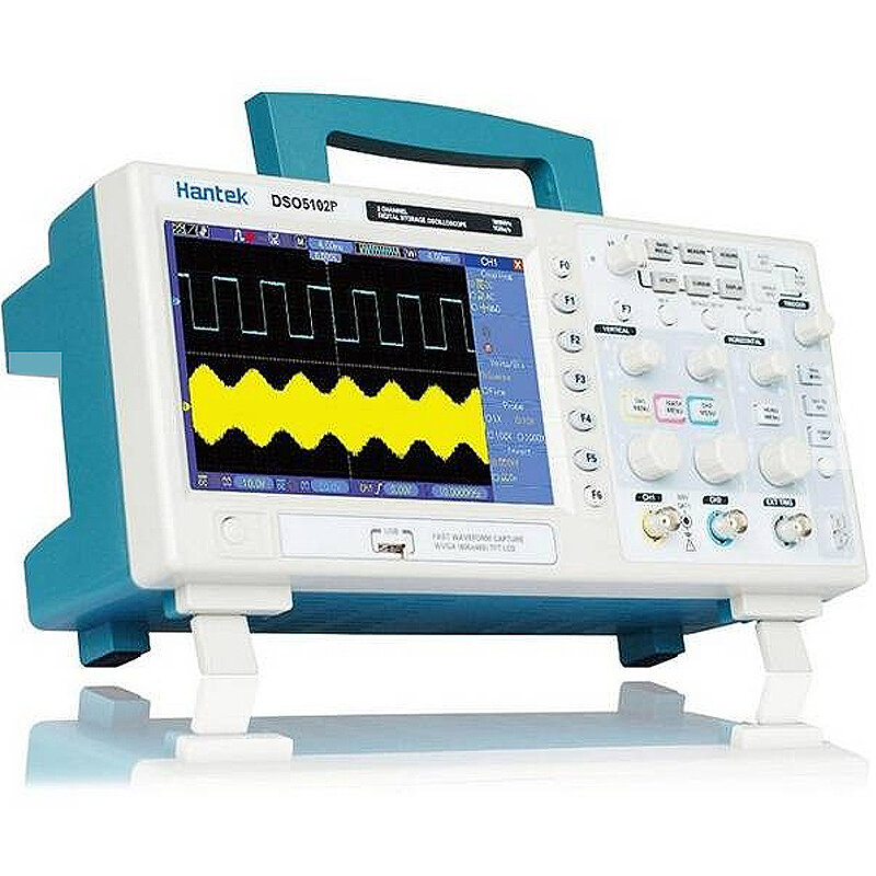
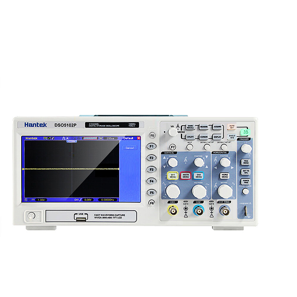

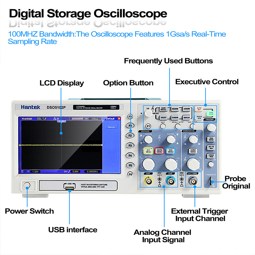
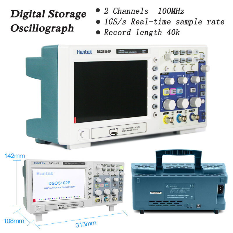
Hantek DSO5102P USB Digital Storage Oscilloscope 2Channels 100MHz 1GSa/s

 Direct purchase from the factory
安全なチェックアウト

 無料ギフト
無料ギフト
 配送ポリシー
 返品ポリシー
無料ギフト
Roymallへようこそ、プレミアムデパートメントストアギフトを購入するための専門ウェブサイトです。私たちはあなたのサポートを高く評価し、感謝の気持ちを込めて、購入ごとに特別な無料ギフトをお届けします。私たちと一緒にショッピングを楽しむことで、ライフスタイルを向上させる高品質な製品を楽しむだけでなく、注文ごとに特別な無料ギフトも受け取ることができます。 私たちのコレクションを探索して、完璧なギフトを見つける準備はできましたか?プレミアムデパートメントストアアイテムのセレクションを閲覧し、注文をして、購入品と一緒に無料ギフトが届くのを楽しみにしてください。配送ポリシー
注文を受領後、商品を安全にお届けするために努めます。配送詳細は確認メールに記載されます。ほとんどの場合、注文は2日以内に処理されます。特別な状況下では、以下のように遅れることがあります:土曜日、日曜日、または祝日に注文をした場合、2日遅れます。通常、飛行機の遅延やその他の環境要因の影響を受けない場合、5〜7営業日(月曜日から金曜日)かかります。私たちの配送サービスは世界中に及ぶため、配送時間はあなたの場所によって異なります。遠隔地や国の場合は数日かかる場合がありますので、お待ちください。1. 返品・交換ポリシー
私たちはroymall.comで購入した商品のみ受け付けます。地元のディストリビューターや他の小売店で購入した商品は返品できません。 最終販売商品や無料ギフトは返品できません。返品の対象となるためには、商品は未使用で受け取ったときと同じ状態でなければなりません。また、元のパッケージに入っている必要があります。返品手順を受け取った後、返品商品をパッケージに詰めて地元の郵便局または別の宅配業者に渡してください。返品または交換商品を受け取った後、3〜5営業日以内に処理します。返金は自動的に元の支払い方法に反映されます。カスタムサイズ、カスタムカラー、カスタムプリントなどのカスタム製品は返品または交換できません。さらにヘルプが必要な場合は、お問い合わせください。 service@roymall.com またはWhatsapp: +8619359849471
2.返金ポリシー
返品パッケージを受け取り、確認した後、全額返金または100%ストアクレジットを受け取ります。返金は自動的に元の支払い方法に反映されます。 配送料や関税、手数料は返金対象外です。パッケージが発送された後、追加の配送料は返金できません。これらの費用を支払う責任があり、私たちはそれらを免除または返金することはできません。返品商品を受け取り、確認した後、返品商品を受け取ったことを通知するメールを送信します。また、返金の承認または拒否についても通知します。返金プロセスに関する問題がある場合は、お問い合わせください。 service@roymall.com またはWhatsapp: +8619359849471Feature:
200/100/70MHz bandwidths
1GSa/s Real Time sample rate
Large (7.0-inch) color display, WVGA(800x480)
Record length up to 40K
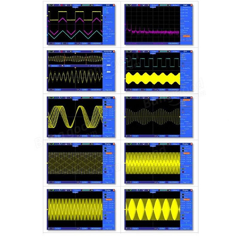
Trigger mode: edge/pulse width/line selectable video/slop/overtime etc.
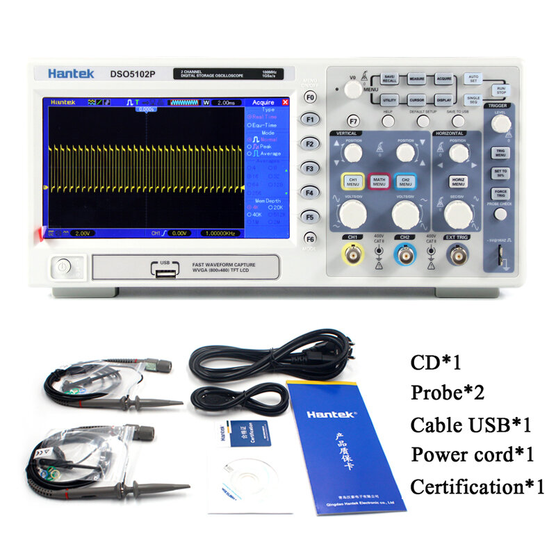
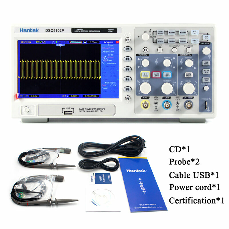
USB host and device connectivity, standard
Multiple automatic measurements
Four math functions, including FFTs standard
Provides software for PC real-time analysis
Model
DSO5102P
Acquisition
Sample Rate
Real-Time Sample: 1GS/s
Acquisition Modes
Normal
Normal data only
Peak Detect
High-frequency and randon glith capture
Average
Wavefom Average, selectable 4,8,16,32,64,128
Inputs
Inputs Coupling
AC, DC, GND
Inputs Impendance
1Mu03a9u00b12%u201620pFu00b13pF
Probe Attenuation
1X, 10X
Supported Probe Attenuation Factor
1X, 10X, 100X, 1000X
Maximum Input Voltage
CAT I and CAT II: 300VRMS (10u00d7), Installation Category;
CAT III: 150VRMS (1u00d7);
Installation Category II: derate at 20dB/decade above 100kHz to 13V peak AC at 3MHz* and above. For non-sinusoidal waveforms, peak value must be less than 450V. Excursion above 300V should be of less than 100ms duration. RMS signal level including all DC components removed through AC coupling must be limited to 300V. If these values are exceeded, damage to the oscilloscope may occur.Horizontal System
Sample Rate Range
500MS/s--1GS/s
Waveform Interpolation
(sin x)/x
Record Length
40K
SEC/DIV Range
4ns/div to 40s/div
Sample Rate and
Delay Time Accuracyu00b150ppm(at over any u22651ms time interval)
Position Range
20ns/div to 80us/div; (-8div x s/div) to 40ms;
200us/div to 40s/div; (-8div x s/div) to 400sTime Measurement Accuracy
(Full Bandwidth)Single-shot, Normal mode:u00b1 (1 sample interval +100ppm u00d7 reading + 0.6ns);
>16 averages:u00b1 (1 sample interval + 100ppm u00d7 reading + 0.4ns);
Sample interval = s/div u00f7 200Vertical System
Vertical Resolution
8-bit resolution, all channel sampled simultaneously
Position Range
2mV/div to 10V/div
Bandwidth
100MHz
Rise Time at BNC( typical)
3.5ns
Analog Bandwidth in Normal and Average modes at BNC or with probe, DC Coupled
2mV/div to 20mV/div, u00b1400mV; 50mV/div to 200mV/div, u00b12V
500mV/div to 2V/div, u00b140V; 5V/div, u00b150VMath
+, -, *, /, FFT
FFT
Windows: Hanning, Flatop, Rectamgular, Bartlett, Blackman;
1024 sample pointBandwidth Limit
20MHz
Low Frequency Response (-3db)
u226410Hz at BNC
DC Gain Accuracy
u00b13% for Normal or Average acquisition mode, 5V/div to 10mV/div;
u00b14% for Normal or Average acquisition mode, 5mV/div to 2mV/divDC Measurement Accuracy,
Average Acquisition ModeWhen vertical displacement is zero, and N u226516:u00b1 (3% u00d7 reading + 0.1div + 1mV) only 10mV/div or greater is selected;
When vertical displacement is not zero, and Nu226516: u00b1 [3% u00d7 (reading + vertical position) + 1% of vertical position + 0.2div]; Add 2mV for settings from 2mV/div to 200mV/div; add 50mV for settings from 200mV/div to 5V/divVolts Measurement Repeatability,
Average Acquisition Modevolts between any two averages of u226516 waveforms acquired under same setup and ambient conditions
Trigger System
Trigger Types
Edge, Video, Pulse, Slope, Over time, Alternative
Trigger Source
CH1, CH2, EXT, EXT/5, AC Line
Trigger Modes
Auto, Normal, Single
Coupling Type
DC, AC, Noise Reject, HF Reject, LF Reject
Trigger Sensitivity
(Edge Trigger Type)DC(CH1,CH2):
1div from DC to 10MHz; 1.5div from 10MHz to 100MHz; 2div from 100MHz to Full;
DC(EXT):
200mV from DC to 100MHz; 350mV from 100MHz to 200MHz;
DC(EXT/5):
1V from DC to 100MHz;1.75V from 100MHz to 200MHz;
AC: Attenuates signals below 10Hz;
HF Reject: Attenuates signals above 80kHz
LF Reject: Same as the DC-coupled limits for frequencies above 150kHz; attenuates signals below 150kHzTrigger Level Range
CH1/CH2: u00b18 divisions from center of screen;
EXT: u00b11.2V;
EXT/5:u00b16VTrigger Level Accuracy( typical)Accuracy is for signals having rise and fall times u226520ns
CH1/CH2: 0.2div u00d7 volts/div within u00b14 divisions from center of screen;
EXT: u00b1 (6% of setting + 40mV);
EXT/5: u00b1 (6% of setting + 200mV);Set Level to 50%(typical)
Operates with input signals u226550Hz
Video Trigger
Video Trigger Type
CH1, CH2: Peak-to-peak amplitude of 2 divisions;
EXT: 400mV;
EXT/5: 2VSignal Formats and Field Rates, Video Trigger Type
Supports NTSC, PAL and SECAM broadcast systems for any field or any line
Holdoff Range
100ns ~ 10s
Pulse Width Trigger
Pulse Width Trigger Mode
Trigger when (< , >, = , or u2260); Positive pulse or Negative pulse
Pulse Width Trigger Point
Equal: The oscilloscope triggers when the trailing edge of the pulse crosses the trigger level.
Not Equal: If the pulse is narrower than the specified width, the trigger point is the trailing edge. Otherwise, the oscilloscope triggers when a pulse continues longer than the time specified as the Pulse Width.
Less than: The trigger point is the trailing edge.
Greater than (also called overtime trigger): The oscilloscope triggers when a pulse continues longer than the time specified as the Pulse WidthPulse Width Range
20ns ~ 10s
Slope Trigger
Slope Trigger Mode
Trigger when (< , > , = , or u2260 ); Positive slope or Negative slope
Slope Trigger Point
Equal: The oscilloscope triggers when the waveform slope is equal to the set slope.
Not Equal: The oscilloscope triggers when the waveform slope is not equal to the set slope.
Less than: The oscilloscope triggers when the waveform slope is less than the set slope.
Greater than: The oscilloscope triggers when the waveform slope is greater than the set slope.Time Range
20ns ~ 10s
Overtime Trigger
Over Time Mode
Rising edge or Falling edge
Time Range
20ns ~ 10s
Alternative Trigger
Trigger on CH1
Internal Trigger: Edge, Pulse Width, Video, Slope
Trigger on CH2
Tools, Industrial & Scientific Ranking
最新のブランドニュースと初回注文15%オフを入手する。


 通貨を選択
通貨を選択 言語を選択
リンク:
言語を選択
リンク:
![[Limited big discount] DG852 Pro Series Function Arbitrary Waveform Generator 50MHz 2CH 625MSa/s High Accuracy Portable Design with 7 inch Touch Screen Low Jitter Rich Modulation for Communication Motor Control](https://static.roymall.com/d/file/mall/titlepic/233/xfhkrh2lnce.jpg?x-oss-process=image/resize,w_237/quality,Q_80/format,webp)


